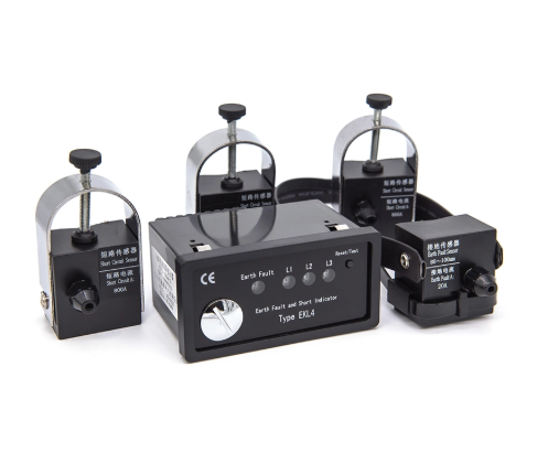

What Affects Earth Fault Passage Indicator Accuracy? How Earth Fault Passage Indicator Accuracy Affects Fault Detection An earth fault passage indicator helps distribution network operators identify faulted sections and reduce unnecessary inspection work. Its accuracy directly influences fault localization, maintenance efficiency, and service restoration. Medium-voltage networks commonly use these devices inside switchgear, ring main units, and cable distribution systems. The equipment monitors electrical signals associated with ground faults and provides indications when specified detection conditions occur. However, accurate detection requires more than identifying abnormal current. The device must distinguish genuine faults from normal electrical variations and temporary disturbances. Incorrect indications may direct technicians toward healthy cable sections, increasing troubleshooting time. Missed faults can delay maintenance and complicate network restoration. Sensor performance, threshold settings, grounding arrangements, and installation conditions collectively determine detection reliability. Each factor requires careful evaluation during equipment selection and commissioning.
How Current Sensor Accuracy Influences Fault Detection
Current sensors provide the electrical measurements necessary for reliable ground fault detection. Core-balance current transformers commonly measure residual current by surrounding all three phase conductors. Under balanced operating conditions, their magnetic contributions largely cancel each other. Ground faults disturb this balance and produce measurable residual current. Sensor sensitivity determines whether the equipment can identify smaller fault currents. Meanwhile, transformation ratio, magnetic characteristics, and measurement linearity influence signal accuracy. Magnetic saturation can distort measurements during high-current disturbances, particularly when sensor specifications do not match operating conditions. External magnetic fields and conductor positioning may introduce additional measurement errors. Engineers should examine the sensor’s specified operating range, accuracy characteristics, and compatibility with the detection controller. Proper sensor selection improves discrimination between genuine ground faults and normal electrical variations throughout distribution networks.
How Earth Fault Passage Indicator Threshold Settings Affect Accuracy
An earth fault passage indicator relies on suitable pickup thresholds to distinguish abnormal residual currents from normal operating conditions. Excessively low thresholds may trigger unwanted indications during switching operations or temporary electrical disturbances. Conversely, high thresholds can prevent detection of faults involving substantial grounding resistance. Detection delays also influence performance because genuine faults and short-duration disturbances exhibit different time characteristics. A longer delay may suppress unnecessary indications but overlook brief fault events. Shorter delays improve response speed while increasing sensitivity to transient signals. Engineers must coordinate threshold settings with system grounding characteristics, feeder capacitance, and expected fault current levels. Reset conditions also require attention because premature clearing can erase useful fault information. Appropriate settings balance detection sensitivity, indication stability, and operational reliability across different network configurations.
How Neutral Grounding Methods Change Detection Performance
Neutral grounding arrangements strongly influence the magnitude and characteristics of ground fault currents. Solidly grounded systems generally produce substantial fault currents, making conventional overcurrent detection suitable under many operating conditions. Resistance-grounded networks limit fault current through an intentional grounding resistor. Their detection requirements depend on resistance values and feeder capacitive contributions. Isolated-neutral systems behave differently because ground fault currents mainly involve the network’s distributed capacitance. Healthy feeders can contribute capacitive current during faults elsewhere in the network. Resonant-grounded systems use compensation reactors to reduce capacitive fault current, creating additional detection challenges. An earth fault passage indicator must therefore match the network’s actual grounding arrangement. Directional measurement or transient detection may improve fault identification when conventional current magnitude thresholds cannot provide adequate selectivity.
How Sensor Installation and Cable Position Affect Measurements
Sensor installation directly affects residual current measurement accuracy in medium-voltage cable systems. Core-balance transformers must surround the intended phase conductors while maintaining the manufacturer’s specified mounting arrangement. Incorrect conductor positioning can introduce measurement errors, particularly during high-current operating conditions. Cable shielding arrangements require additional attention because grounding conductors may carry currents that influence sensor readings. For suitable single-point bonded installations, technicians must route shield grounding leads according to the specified sensing arrangement. Otherwise, unwanted current contributions may distort the measured residual signal. Sensor orientation and mechanical stability also influence consistent operation. Loose mounting components can create vibration-related problems or disturb cable positioning over time. Installers should inspect conductor clearance, cable bending, and available installation space. Careful installation reduces measurement uncertainty and supports dependable operation during actual electrical faults.
Comparing Electrical Factors That Influence Detection Accuracy
Detection accuracy depends on several electrical characteristics that interact rather than operate independently. Sensor sensitivity affects the minimum measurable residual current, while threshold selection determines which measurements trigger indications. Network grounding establishes the expected fault current magnitude and phase relationships. Cable capacitance becomes particularly significant in isolated and compensated networks because healthy feeders contribute current during ground faults. Fault resistance introduces another variable by limiting available current and reducing detection margins. Supply voltage stability can also affect devices that require auxiliary power for signal processing and indication functions. Engineers should assess these conditions collectively before establishing operating parameters. For example, increasing sensor sensitivity cannot compensate for unsuitable directional logic or incorrect cable shield installation. Reliable detection requires coordinated sensor characteristics, measurement settings, and network-specific operating assumptions throughout the equipment’s service life.
Why Directional and Non-Directional Detection Produce Different Results
Non-directional detection evaluates fault-related current measurements without determining their direction relative to the installation point. This approach can perform effectively when fault currents clearly exceed normal feeder contributions. However, isolated-neutral networks may produce significant capacitive currents through healthy feeders during faults elsewhere. Directional detection offers additional discrimination by evaluating current relationships against a suitable voltage reference. Depending on the system, the controller may examine residual current magnitude, residual voltage, and their phase-angle relationship. Accurate polarity connections become essential because reversed measurement references can produce incorrect directional decisions. Distributed generation may introduce further complications by changing fault current contributions and network operating conditions. An earth fault passage indicator with appropriate directional capabilities can improve localization where current magnitude alone provides insufficient discrimination.
How Transient Faults and Electrical Interference Affect Indications
Transient electrical disturbances can complicate fault detection in medium-voltage distribution networks. Switching operations, cable energization, and intermittent insulation breakdown may produce rapidly changing current signals. Some disturbances resemble genuine faults when detection algorithms examine only instantaneous current magnitude. Harmonic distortion introduces additional measurement complexity because nonfundamental frequency components can affect signal interpretation. Electromagnetic interference may also influence electronic circuits and communication connections inside electrical cabinets. Digital filtering helps suppress unwanted signal components while preserving relevant fault information. However, excessive filtering can delay detection or obscure short-duration events. Sampling frequency, measurement resolution, and detection logic must therefore support the intended operating conditions. Intermittent faults require particular attention because repeated brief events may precede permanent insulation failure. Appropriate signal processing improves indication stability without unnecessarily reducing sensitivity to genuine faults.
Practical Installation and Calibration Checks for Reliable Operation
Commissioning verifies whether the installed equipment performs correctly under the network’s intended operating conditions. Technicians should inspect sensor placement, electrical connections, measurement settings, and indication functions before energizing the completed installation. Where applicable, secondary current injection can verify pickup thresholds and operating delays without creating actual network faults. Directional equipment may require coordinated current and voltage injection to evaluate phase relationships. Tests should also confirm output contacts, local displays, remote signaling, and reset behavior. IEC 62689-1:2016 establishes general requirements and testing principles for fault passage indication equipment. IEC 62689-2:2016 addresses system-level application considerations, including network grounding and fault detection arrangements. These documents provide relevant technical references when selecting and verifying suitable equipment. Commissioning records should preserve actual settings and test results for future maintenance comparisons.
Essential Commissioning Checklist
- Verify current sensor orientation and mounting stability.
- Confirm correct phase conductor and cable shield routing.
- Check residual current measurement accuracy.
- Validate pickup thresholds against expected fault currents.
- Test detection delays and reset conditions.
- Verify directional measurement polarity where applicable.
- Inspect auxiliary power connections and voltage compatibility.
- Test local indication and remote communication outputs.
- Record final settings and commissioning results.
How Environmental Conditions Affect Long-Term Detection Reliability
Environmental conditions influence electronic measurement stability and long-term equipment reliability. High temperatures may accelerate electronic component aging and affect certain sensor characteristics. Low temperatures can influence display operation, battery performance, and mechanical components. Humidity and condensation increase the risk of corrosion, insulation deterioration, and unintended leakage paths. Vibration from nearby switching equipment may loosen electrical connections or sensor mounting hardware. Electromagnetic disturbances can also affect signal processing when installation practices provide inadequate separation or shielding. An earth fault passage indicator should meet environmental requirements appropriate to its intended installation location. Manufacturers typically specify operating temperature ranges, humidity limits, and applicable enclosure protection ratings. Maintenance personnel should inspect wiring, mounting components, and visible signs of deterioration. Regular checks help preserve reliable measurements throughout changing seasonal and operational conditions.
Key Factors for Maintaining Accurate Fault Passage Indication
Reliable fault passage indication requires coordinated electrical design, installation practices, and periodic verification. Accurate sensors provide the foundation for residual current measurement, but appropriate detection settings remain equally important. Grounding arrangements determine fault current characteristics and influence the suitability of directional measurement. Correct cable installation prevents unwanted measurement contributions from shield grounding conductors and surrounding electrical equipment. Signal processing must distinguish genuine faults from temporary disturbances without sacrificing necessary sensitivity. Engineers should verify these interactions during initial commissioning and following significant network modifications. Changes involving feeder length, cable configuration, grounding equipment, or distributed generation can alter fault detection conditions. Maintenance records should document measurement settings, test observations, and equipment condition. A systematic approach reduces false indications, improves fault localization, and supports dependable medium-voltage distribution network operation.
Frequently Asked QuestionsWhat Causes an Earth Fault Passage Indicator to Give False Signals?
False indications can result from unsuitable pickup thresholds, sensor installation errors, and transient electrical disturbances. Excessively sensitive thresholds may respond to normal feeder charging currents or switching events. Incorrect cable shield routing can introduce unwanted current contributions into residual current measurements. Electromagnetic interference and unsuitable signal filtering may also influence electronic detection circuits. In isolated-neutral networks, capacitive currents from healthy feeders can complicate non-directional fault identification. Engineers should compare recorded indications with actual network operating conditions and protection events. Checking sensor connections, threshold values, detection delays, and directional settings helps identify potential causes. Proper commissioning and periodic verification reduce unwanted indications and improve operational reliability.
How Does Grounding Resistance Affect Fault Passage Detection?
Grounding resistance directly influences the current available during a phase-to-ground fault. Higher resistance generally limits fault current, making low-current detection capability increasingly important. Lower grounding resistance permits greater current flow, although actual values depend on system impedance and network configuration. In resistance-grounded systems, engineers must consider both intentional neutral resistance and feeder capacitive contributions. High-resistance faults can produce currents close to normal residual current levels. Consequently, conventional threshold detection may struggle to distinguish these events reliably. Directional measurement can improve selectivity when suitable current and voltage references are available. Correct sensor selection and coordinated settings help maintain dependable fault identification across different grounding arrangements.
How Often Should Fault Passage Indicators Be Tested?
Testing frequency depends on manufacturer recommendations, operating conditions, maintenance policies, and applicable utility requirements. Every new installation should undergo commissioning verification before normal operation. Additional testing becomes appropriate following sensor replacement, controller configuration changes, or significant modifications to network grounding arrangements. Periodic maintenance should include visual inspection, electrical connection checks, and functional verification where practical. Technicians should examine indication behavior, reset functions, auxiliary power, and communication outputs. Equipment installed in demanding environments may require more frequent inspections. Maintenance teams should also review unexplained fault indications and compare them with protection system records. Documented testing results support long-term reliability assessments and help identify developing equipment problems.